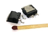
Photo from wikipedia
This paper presents a simple resistance-to-time converter. It consists of two voltage comparators, a ramp voltage generator, two logic gates and impulse voltage calibrators. A square-wave generator circuit is suggested… Click to show full abstract
This paper presents a simple resistance-to-time converter. It consists of two voltage comparators, a ramp voltage generator, two logic gates and impulse voltage calibrators. A square-wave generator circuit is suggested in this paper. The design is simple and independent of the OPAMP offset issues. The resulting square-wave is rectified to get its DC equivalent and to a triangular output; the two outputs are applied to a comparator for generating a digital output with a duty cycle proportional to a change in resistance upon which is dependent the DC.
Journal Title: Indonesian Journal of Electrical Engineering and Computer Science
Year Published: 2018
Link to full text (if available)
Share on Social Media: Sign Up to like & get
recommendations!